Design Standard
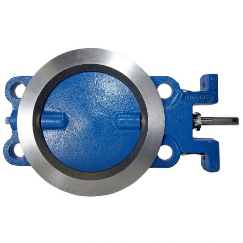
The PDC “Econotrol” series butterfly valve is available in sizes from 2″ thru 14″ in a combination of materials and optional features suitable for most mid-range differential pressures and service conditions.
Specifications
Size Range:
2" thru 14" for 125/150 lb. Flanging
Temperature:
To 450°F (232°C) with standard materials
Pressure Rating:
Varies with size. See Econotrol Series 09 Brochure
Design Features
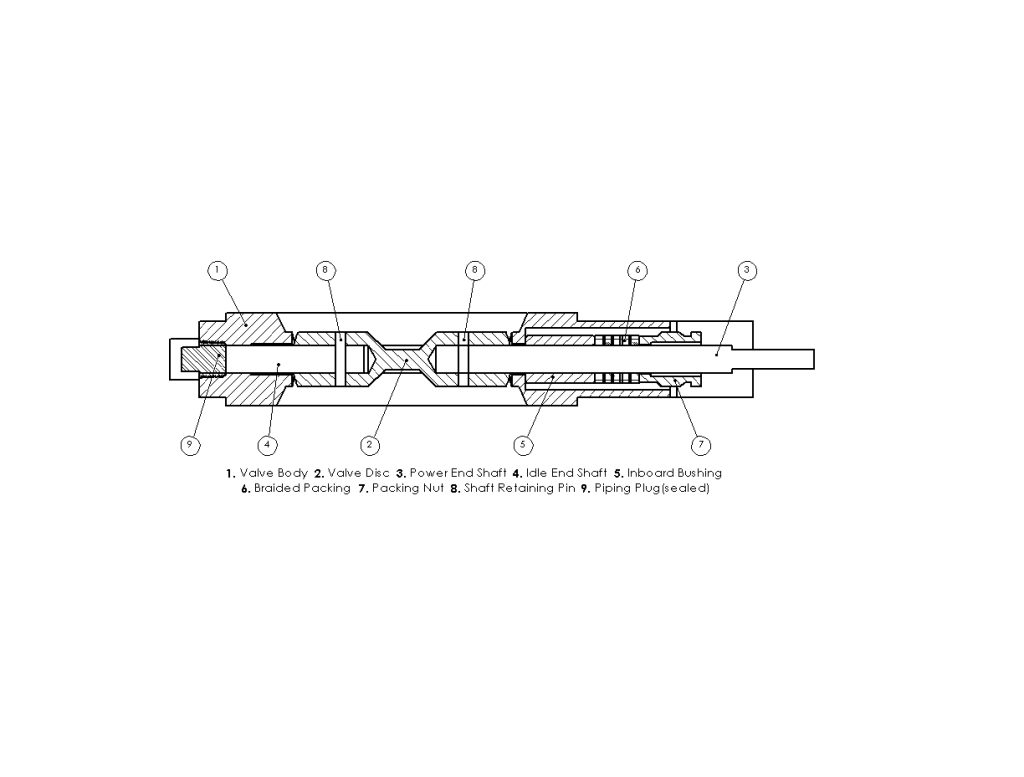
- Inboard bushings of graphited bronze for long life, non-freezing, low torque characteristics.
- Close tolerance machining for minimal leakage and dependable flow characteristics.
- Adjustable packing-Graphited TEFLON® Braid. Valves can be repacked without removal from line. Rugged mounting pads drilled and tapped for ease of installing actuating equipment and accessories.
- Flatted, keywayed or hexed ends on shafts are available to facilitate factory or field mounting of all types of actuating equipment. (Flatted shaft shown).
- Lightweight, solid ring, wafer design for ease of installation. Four holes to insure proper alignment without transfer of pipe stresses to the valve body.
- Contoured bore improves flow characteristics.
Applications
- Blower Equipment
- Compressor Equipment
- Boiler Equipment
- Environmental Systems
- H.V.A.C
- Industrial Process Furnaces
- Oil and Gas/Refining
- Power Generation/Co-Generation
- Water & Sewage
- Stationary Engines
- Chemical Equipment
- Mining Equipment
- Gas Recovery Systems
Standard Materials and Seat Construction
| Body: | Cast Iron |
| Disc: | Cast Iron |
| Shaft: | 416 Stainless Steel |
| Seat: | Swing-thru |
| Bushing: | Graphited Bronze (2″-14″) |
| Packing: | Graphited Teflon Braid |
| Packing Nut: | Stainless Steel |
Optional Materials and Seat Construction
| Body: | No Option |
| Disc: | Carbon Steel, 316 Stainless Steel, 304 Stainless Steel |
| Shaft: | 316 Stainless Steel, 304 Stainless Steel, Incoloy, Monel |
| Seat: | No Option |
| Bushing: | 304 Stainless Steel, Glass Filled Teflon, Metcar |
| Packing: | Pure Teflon Braid, Teflon V-Ring |
| Packing Nut: | No Option |
Chart or Graph
*Torque, Lb-In, Required for PDC Swing Thru Butterfly Valves with Disc in Closed Position for Temperatures up to 450° Fahrenheit
*Below torques only apply to normal clean service conditions.
| VALVE SIZE | PRESSURE DROP ACROSS DISC IN CLOSED POSITION, PSI |
|---|
| 0.5 | 1 | 5 | 10 | 15 | 20 | 25 | 30 | 40 | 50 | 60 | 70 | 80 | 90 | 100 | 125 | 150 |
| 2 | 50 | 50 | 52 | 53 | 55 | 56 | 58 | 59 | 62 | 65 | 65 | 71 | 74 | 77 | 80 | 88 | 95 |
| 2.5 | 50 | 51 | 53 | 55 | 58 | 60 | 63 | 65 | 70 | 75 | 80 | 85 | 90 | 95 | 100 | 113 | 125 |
| 3 | 50 | 51 | 54 | 57 | 61 | 64 | 68 | 71 | 78 | 85 | 92 | 99 | 106 | 113 | 120 | 138 | 155 |
| 4 | 51 | 52 | 59 | 67 | 76 | 84 | 93 | 101 | 118 | 135 | 152 | 169 | 186 | 203 | 220 | 263 | – |
| 5 | 51 | 53 | 63 | 75 | 88 | 100 | 113 | 125 | 150 | 175 | 200 | 225 | 250 | 275 | 300 | – | – |
| 6 | 52 | 54 | 69 | 88 | 107 | 126 | 145 | 164 | 202 | 240 | 278 | 316 | 354 | – | – | – | – |
| 8L | 54 | 58 | 88 | 125 | 163 | 200 | 238 | – | – | – | – | – | – | – | – | – | – |
| 8H | 124 | 128 | 158 | 195 | 233 | 270 | 308 | 345 | 420 | 495 | 570 | 645 | 720 | 795 | – | – | – |
| VALVE SIZE | PRESSURE DROP ACROSS DISC IN CLOSED POSITION, PSI |
|---|
| 0.5 | 1 | 3 | 5 | 8 | 10 | 13 | 15 | 20 | 25 | 30 | 35 | 40 | 45 | 50 | 60 | 70 |
| 10 | 129 | 137 | 171 | 205 | 256 | 290 | 341 | 375 | 460 | 545 | 630 | 715 | 800 | 885 | 970 | 1140 | 1310 |
| 12 | 132 | 143 | 189 | 235 | 304 | 350 | 419 | 465 | 580 | 695 | 810 | 925 | 1040 | 1155 | 1270 | – | – |
| 14 | 139 | 157 | 231 | 305 | 416 | 490 | 601 | 675 | 860 | 1045 | 1230 | – | – | – | – | – | – |
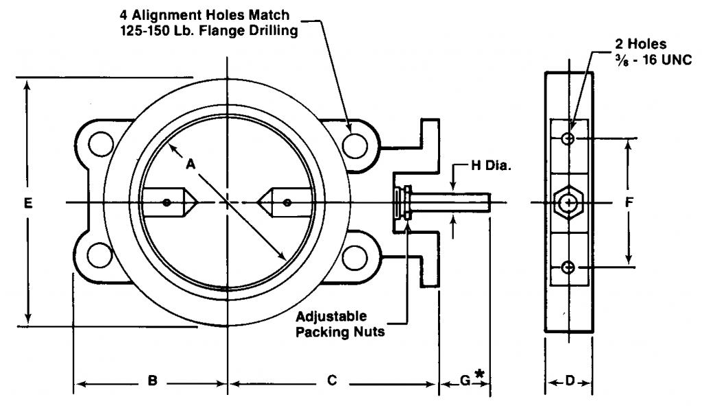
Typical Dimensions: 2″ thru 14″
| Dimensions: Inches |
|---|
| Size (inch) | A | B | C | D | E | F | H | Max. Delta-P (PSI) | Approx. Wt. (Lbs) |
|---|
| 2 | 2 | 2-3/4 | 5-3/8 | 1-1/2 | 3-7/8 | 4-1/4 | 1/2 | 150 | 9 |
| 2.5 | 2-1/2 | 3 | 5-5/8 | 1-1/2 | 4-5/8 | 4-1/4 | 1/2 | 150 | 10 |
| 3 | 3 | 3-1/8 | 5-7/8 | 1-1/2 | 5-7/4 | 4-1/4 | 1/2 | 150 | 11 |
| 4 | 4 | 4-1/4 | 6-3/8 | 1-1/2 | 6-3/8 | 4-1/4 | 1/2 | 125 | 12 |
| 5 | 5 | 4-7/8 | 6-7/8 | 1-1/2 | 7-1/2 | 4-1/4 | 1/2 | 100 | 15 |
| 6 | 6 | 5-3/8 | 7-3/8 | 1-1/2 | 8-1/2 | 4-1/4 | 1/2 | 80 | 17 |
| 8L | 8 | 6-1/2 | 8-3/8 | 1-1/2 | 10-3/4 | 5-1/8 | 1/2 | 25 | 23 |
| 8H | 8 | 6-1/2 | 9-5/8 | 1-7/8 | 10-3/4 | 5-1/8 | 3/4 | 90 | 32 |
| 10 | 10 | 8 | 10-5/8 | 1-7/8 | 13 | 5-1/8 | 3/4 | 70 | 40 |
| 12 | 12 | 9-1/2 | 11-5/8 | 1-7/8 | 15-1/4 | 5-1/8 | 3/4 | 50 | 50 |
| 14 | 13-1/8 | 10-1/2 | 12-1/8 | 1-7/8 | 16-1/2 | 5-1/8 | 3/4 | 30 | 70 |
* “G” Length and configuration of the shaft end will vary to accommodate specific actuators. Refer to the accessory section for typical flatted, keywayed, and hexed end configurations available. MAX. ∆P is based on 0° disc position, using standard materials of construction at a maximum temperature of 450° Fahrenheit. Consult factory for MAX. ∆P for elevated temperatures.


