Flanged End - Series: 39

Design Standard
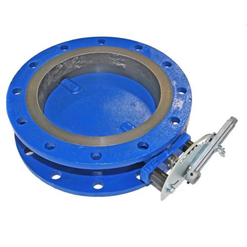
The PDC “Flanged” series butterfly valve is available in sizes from 4″ thru 14″ in a combination of materials and optional features suitable for most mid-range differential pressures and service conditions.
Specifications
Design Features
- Inboard bushings of graphited bronze for long life, non-freezing, low torque characteristics.
- Close tolerance machining for minimal leakage and dependable flow characteristics.
- Adjustable packing Graphited TEFLON ® Braid. Valves can be repacked without removal from line.
- Rugged mounting pads drilled and tapped for ease of installing actuating equipment and accessories.
- Flatted, keywayed or hexed ends on shafts are available to facilitate factory or field mounting of all types of actuating equipment.
- Lightweight, full faced flange designed for ease of installation. The full flanged drilling will allow for dead end flange connection.
- Contoured bore improves flow characteristics.
Applications
- Blower Equipment
- Compressor Equipment
- Boiler Equipment
- Environmental Systems
- V.A.C
- Industrial Process Furnaces
- Oil Gas/Refining
- Power Generation/Co-Generation
- Water & Sewage
- Stationary Engines
- Chemical Equipment
- Mining Equipment
- Gas Recovery Systems
Standard Materials and Seat Construction
| Body: | Ductile Iron |
| Disc: | Cast Iron |
| Shaft: | 416 Stainless Steel |
| Seat: | Swing-thru |
| Bushing: | Graphited Bronze |
| Packing: | Graphited Teflon Braid |
| Packing Nut: | Brass |
Optional Materials and Seat Construction
| Body: | High Temperature Iron, Carbon Steel, 316 Stainless Steel, 304 Stainless Steel |
| Disc: | Carbon Steel, 316 Stainless Steel, 304 Stainless Steel |
| Shaft: | 316 Stainless Steel, 304 Stainless Steel, Incoloy, Monel |
| Seat: | Angle |
| Bushing: | 316 Stainless Steel, 304 Stainless Steel, Glass Filled Teflon, Metcar |
| Packing: | Pure Teflon Braid, Teflon V-Ring |
| Packing Nut: | 316 Stainless Steel |

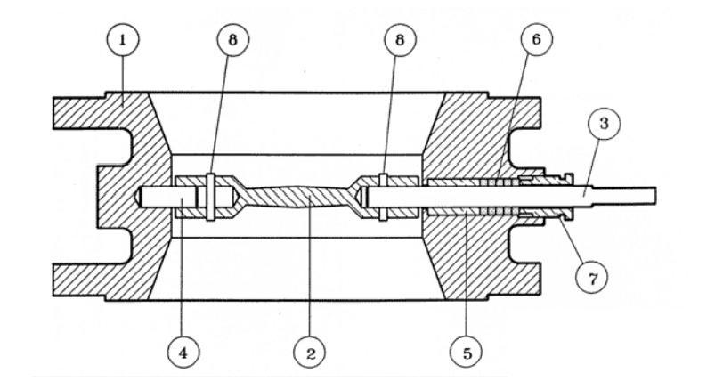
- Body
- Disc
- Power Shaft
- Idle Shaft
- Bushing
- Braided Packing
- Packing Nut
- Shaft Retaining Pin
Chart or Graph
*Torque, Lb-In/PSI, Required for PDC swing thru valves with disc in closed position for temperatures up to 450 degrees F
*Below Torques only apply to normal clean service conditions
| VALVE SIZE | PRESSURE DROP ACROSS DISC IN CLOSED POSITION, PSI | ||||||||||||||||
|---|---|---|---|---|---|---|---|---|---|---|---|---|---|---|---|---|---|
| 0.5 | 1 | 2 | 3 | 4 | 5 | 6 | 8 | 10 | 12 | 14 | 16 | 18 | 20 | 22 | 24 | 25 | |
| 4 | 51 | 52 | 53 | 55 | 57 | 59 | 60 | 64 | 67 | 70 | 74 | 77 | 81 | 84 | 87 | 91 | 93 |
| 5 | 51 | 53 | 55 | 58 | 60 | 63 | 65 | 70 | 75 | 80 | 85 | 90 | 95 | 100 | 105 | 110 | 113 |
| 6 | 52 | 54 | 58 | 61 | 65 | 69 | 73 | 80 | 88 | 96 | 103 | 111 | 118 | 126 | 134 | 141 | 145 |
| 8 | 124 | 128 | 135 | 143 | 150 | 158 | 165 | 180 | 195 | 210 | 225 | 240 | 255 | 270 | 285 | 300 | 308 |
| 10 | 129 | 137 | 154 | 171 | 188 | 205 | 222 | 256 | 290 | 324 | 358 | 392 | 426 | 460 | 494 | 528 | 545 |
| 12 | 132 | 143 | 166 | 189 | 212 | 235 | 258 | 304 | 350 | 396 | 442 | 488 | 534 | 580 | 626 | 672 | 695 |
| 14 | 139 | 157 | 194 | 231 | 268 | 305 | 342 | 416 | 490 | 564 | 638 | 712 | 786 | 860 | 934 | 1008 | 1045 |
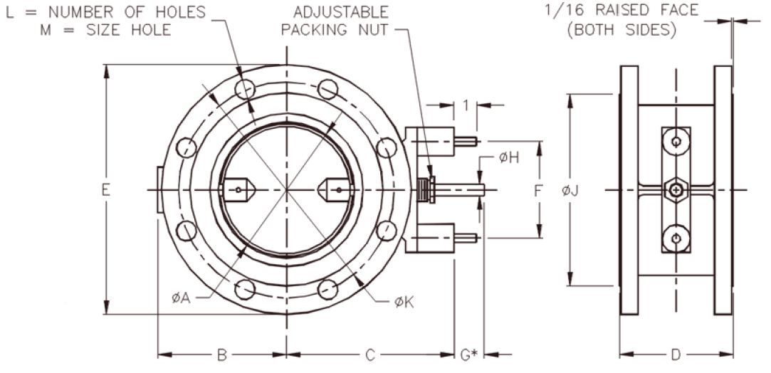
Typical Dimensions: 4″ thru 14″

| SIZE | A | B | C | D | E | F | H | J | K | L | M | Max ΔP | Approx wt (Lb.) |
|---|---|---|---|---|---|---|---|---|---|---|---|---|---|
| 4 | 4 | 4-1/2 | 6-3/8 | 5 | 9 | 4-1/4 | 1/2 | 6-3/6 | 7-1/2 | 8 | 3/4 | 25 | 35 |
| 5 | 5 | 5 | 6-7/8 | 5 | 10 | 4-1/4 | 1/2 | 7-1/2 | 8-1/2 | 8 | 7/8 | 25 | 41 |
| 6 | 6 | 5-1/2 | 7-3/8 | 5 | 11 | 4-1/4 | 1/2 | 8-1/2 | 9-1/2 | 8 | 7/8 | 25 | 51 |
| 8 | 8 | 7-3/4 | 9-5/8 | 5-1/2 | 13-1/2 | 5-1/8 | 3/4 | 10-5/8 | 11-3/4 | 8 | 7/8 | 25 | 72 |
| 10 | 10 | 8-3/4 | 10-5/8 | 5-1/2 | 16 | 5-1/8 | 3/4 | 12-3/4 | 14-1/4 | 12 | 1 | 25 | 91 |
| 12 | 12 | 9-3/4 | 11-5/8 | 5-1/2 | 19 | 5-1/8 | 3/4 | 15 | 17 | 12 | 1 | 25 | 120 |
| 14 | 13-1/8 | 10-1/2 | 12-1/8 | 5-1/2 | 21 | 5-1/8 | 3/4 | 16-1/4 | 18-3/4 | 12 | 1-1/8 | 25 | 140 |
Cv Values for PDC Swing Thru Butterfly Valves
By definition, Cv is the flow coefficient of a control device or flow restriction. Cv is defined as the number of US gallons of 60°F water per minute which will flow through the given restriction with a one pound per square inch pressure drop.
Cv Values
(Flow in GPM of 60°F water at 1 psi pressure drop, specific gravity=1)
| VALVE SIZE | Disc Angle, Degress | ||||||||
|---|---|---|---|---|---|---|---|---|---|
| 10 | 20 | 30 | 40 | 50 | 60 | 70 | 80 | 90 | |
| 4 | 13 | 28 | 54 | 98 | 159 | 257 | 391 | 550 | 747 |
| 5 | 21 | 43 | 88 | 158 | 265 | 429 | 636 | 913 | 1272 |
| 6 | 30 | 63 | 126 | 228 | 382 | 632 | 955 | 1370 | 1999 |
| 8 | 53 | 111 | 225 | 406 | 680 | 1125 | 1698 | 2591 | 3853 |
| 10 | 83 | 174 | 351 | 635 | 1063 | 1758 | 2655 | 4052 | 6361 |
| 12 | 120 | 252 | 506 | 915 | 1531 | 2533 | 3826 | 5835 | 9164 |
| 14 | 143 | 302 | 606 | 1096 | 1835 | 3035 | 4584 | 6992 | 10981 |

